


All Products
-
Xtruck Truck Diagnosis
-
Heavy Duty Truck Diagnostic Scanner
-
Truck Diagnostic Tool
-
Mercedes Benz Star Diagnosis Tool
-
Vocom Diagnostic Tool
-
Construction Scanner
-
Excavator Scanner
-
Forklift Diagnostic Tools
-
Agricultural Diagnostic Tools
-
Truck Diagnostic Software
-
Car Diagnostics Scanner
-
Multi Brand Diagnostic Tool
-
Excavator Parts
-
BMW Diagnostics Tool
-
Launch x431 Master Scanner
-
Autel Diagnostic Tools
-
Auto Diagnostics Software
-
Gm Tech2 Scanner
-
Automotive ECU Programmer
-
Code Scanners For Cars
-
Garage Equipment Repairs
-
Car Electronics Products
-
Automotive Locksmith Tools
-
Transponder Chip Programmer
-
Automotive Key Programmer
-
Auto Transponder Chip
-
Car Key Cutting Machines
-
Car Lock Decoder
-
Copying Machines
-
Remote Control Duplicator
-
GPS Navigation For Car
-
Car Stereo System
-
Car Multimedia Player
-
Car Radio Head Unit
-
 Jim.MExcellent Shipping. very fast response to questions AAA+++++ seller will do business with again.
 -
Giovanni S.Super venditore,affidabile,veloce sulla spedizione.....insomma tutto ok:-)
-
Rayner LThank you. I am very happy with the product. Everything arrived in excellent condition.
Contact Person :
Sara,Coco,Shirley,Eno, Vicky
Phone Number :
+86-0755-25403809
Whatsapp :
+8613684920569
3055B SKS-3055B ECU Signal Generator Car Tuning Software For Auto ECU Repair


| Place of Origin | China |
|---|---|
| Brand Name | JIU |
| Certification | CE & FCC |
| Minimum Order Quantity | 1pcs |
| Price | Negotiation |
| Packaging Details | In Cartoon |
| Payment Terms | T/T, Money Gram |
| Supply Ability | In Stock |

Contact me for free samples and coupons.
Whatsapp:0086 18588475571
Wechat: 0086 18588475571
Skype: sales10@aixton.com
If you have any concern, we provide 24-hour online help.
xProduct Details
| High Light | diagnostic car tool,car diagnostic equipment |
||
|---|---|---|---|
Product Description
3055B SKS-3055B ECU Signal Generator Car Tuning Software For Auto ECU Repair
3055B SKS-3055B ECU Signal Generator
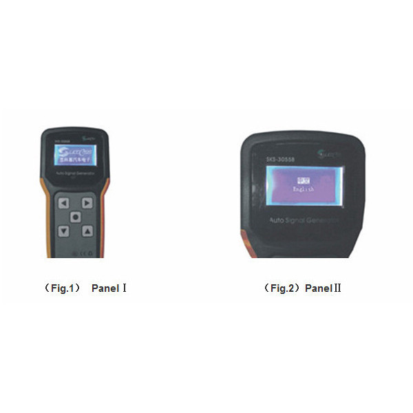
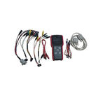
II. Description of the Panel
![]()
III. Instrument Features
1, Signal Characteristics Adjustment: Adjust the amplitude, frequency, phase, X + Y, waveform and other indicators, while the signal output. This is very convenience for auto ECU repair.
2, Multi-output signal: Made by high-performance microprocessors, can output 7 signals simultaneously.
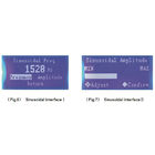
3, Human control interface: By the simple design ideas, 128*64 LCD, Bilingual display, easy to operate.
![]()
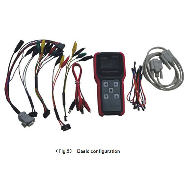
4, Cables: Supporting common sensor cables, for various models.
![]()
IV. Function Introduction
This instrument can simultaneous output sinusoidal, square-wave, X+Y signal, voltage signal, oxygen sensor signal, resistance signal and PWM signal, which includes all the common signal characteristics of automotive sensors.
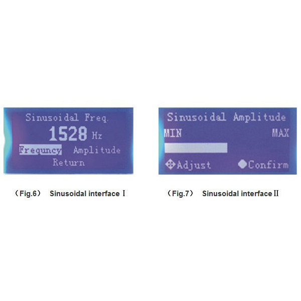
1.Sinusoidal signal:
* 1--2KHz Frequency regulation;
* Signal Single-ended output to ground;
* 5Vpp--18Vpp Amplitude adjustment.
![]()
Mainly used for simulate the rotating speed, wheel speed, vehicle speed signals, which was generated by magnetic sensor.
2. Square-wave Signal:
* 1--20KHz Frequency regulation;
* Signal Single-ended output to ground;
* 5Vpp--9Vpp Amplitude adjustment.
![]()
Used for simulate the rotating speed, wheel speed, camshaft position and air-flow signals, which was generated by Hall sensor and photoelectric sensor.
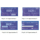
3. X+Y Signal
* 1--2KHz Frequency regulation;
* 5Vpp--18Vpp Amplitude adjustment;
* 1--60 X+Y signal adjustment.
* 1--3 X+Y signal adjustment.
* 0°, 180° Phase position adjustment.
* X+Y signal outputted by Square-Ground, Sine-Ground and Sine-Couple, easy to simulate various crank signals.
* Sine-wave and Square-wave switched while Signal-Ground output.
![]()
Used for simulate the X+Y signal of Magneto electric, photo electricity and Hall sensors.
4. Voltage Signal:
* 0--5V Voltage adjustment.
* Output voltage precision 0.02V.
* Signal Single-ended output to ground
![]()
Used for simulate the voltage signal of Throttle Position, MAP and EGR Valve Position Sensors.
5. Oxygen Sensor Signal:
* The 0.1V, 0.9V Oxygen ion Dilute and Concentrate can be switched at anytime.
* Signal Single-ended output to ground
![]()
Used for simulate oxygen ion concentrate signal by kinds of oxygen sensors.
6. Resistance Signal
* Precision Multi-turn pointer potentiometer.
* 0--10K Ten loop output, MIN 22Ω
![]()
Used for output signal of coolant temperature, intake air temperature and temperature sensors. It must be realized by simulate resistance signal.
7. PWM Signal
* 2 Hz -- 999+-1 Hz Frequency can be adjusted independently.
* 1% -- 99%+-1% Duty cycle can be adjusted independently.
* Signal Single-ended output to ground.
* 9Vpp amplitude fixed output.
![]()
Used for simulate the ignition control signal, fuel injection control signal, camshaft position signal, EGR control signal and some other pulse signals.
V. Instructions
1, Power
Use outlet power, switch leader cable (ACCES.1) into button Nine-pin jack. Use the power line (ACCES.2) can easily connected with 12V car battery; Use stabilized voltage supply, work condition: current greater than 2A, Voltage between 10V-15V. Use 220V/12V power adapter, please NOTE: Current ABOVE 1A, Voltage shall NOT above 15V. Power output plug should match with the instrument.
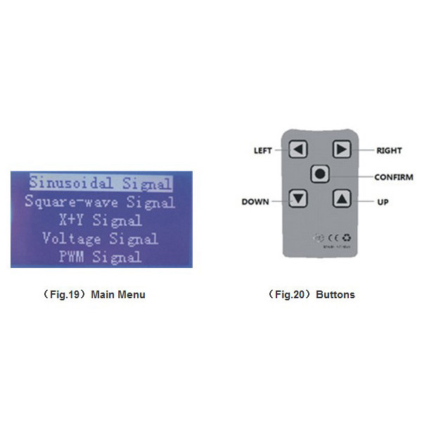
2, Button and Main Men
![]()
3, Generation of sinusoidal signal
After power, choose "Sinusoidal signal" (Fig.19), press" CONFIRM" into Sinusoidal interface (Fig.6), choose "Frequency" and "Amplitude".
* Adjust Frequency: After enter (Fig.6), use "LEFT" and "RIGHT" choose frequency value; use "UP" and "DOWN" choose magnitude. Press CONFIRM after the adjustment.
* Adjust Amplitude: After enter (Fig.7), use "LEFT" and "RIGHT" choose Sinusoidal signal amplitude; use "UP" and "DOWN" choose range.
* Signal output: Choose square-wave and Sinusoidal output cables(ACCES.3), the BLUE wire shall generate the Single-ended output to ground Sinusoidal Signal by( Black clamp)
4, Generation of Square-wave Signal
After power, choose "Square-wave Signal" (Fig.19), press "CONFIRM" into Square-wave Signal interface (Fig.8), choose "Frequency" and "Amplitude".
* Adjust Frequency: After enter (Fig.8), use "LEFT" and "RIGHT" choose frequency value; use "UP" and "DOWN" choose magnitude. Press CONFIRM after the adjustment.
* Adjust Amplitude: After enter (Fig.9), use "LEFT" and "RIGHT" choose Square-wave Signal amplitude; use "UP" and "DOWN" choose range.
* Signal output: Choose square-wave and Sinusoidal output cables (ACCES.3), the GREEN wire shall generate the Single-ended output to ground square-wave Signal by Black clamp.
5, Generation of X+Y Signal
After power, choose "X+Y Signal" (Fig.19), press "CONFIRM" into X+Y Signal interface (Fig.10), choose "Frequency" "Amplitude" and "Waveform".
* Adjust Frequency: Choose "Frequency" into "X+Y Signal Interface" (Fig.10, 11, 12), use "LEFT" and "RIGHT" choose digit; use "UP" and "DOWN" choose range. Press CONFIRM after the adjustment.
* Adjust Amplitude: Choose "Amplitude" into "X+Y signal interface" (Fig.13), use "LEFT" and "RIGHT" choose amplitude; use "UP" and "DOWN" choose range.
* Adjust Waveform: Choose " Waveform" into X+Y signal interface (Fig.10, 11, 12), cursor moves to "58+2", use "LEFT" and "RIGHT" choose X and Y, use "UP" and "DOWN" choose signal X(1-60) or Y (1-3); According to the actual vehicle signal characteristics, use LEFT button move the cursor to "Sine-Ground", use "UP" and "DOWN" choose the output form "Sine-Ground" "Sine-Couple" and "Square-wave". Move cursor to "POS". use "UP" and "DOWN" chooses "POS". and "REV". Also can use the oscillograph to observe the changes of all the signal signature. This feature is suitable for ECU dynamic test.
Signal Output: Use the X+Y output cables (ACCES.4), choose "Sine-ground", the GREEN WITH WHITE LINE wire shall generate the Single-ended output to ground Sine X+Y Signal by BROWN clamp; Choose "Square-wave" the GREEN WITH WHITE LINE wire shall generate the Single-ended output to ground Square X+Y Signal by BROWN clamp; Choose "Sine-Couple" the GREEN WITH WHITE LINE wire and BROWN wire shall generate magnetic X+Y signal: GREEN output (XY+) and BROWN output (XY-).
6, Generation of Voltage signal
After power, choose (Voltage signal (Fig.19), press "CONFIRM" into Voltage Signal interface (Fig.21), "Voltage signal" and "Oxygen Sensor Signal" belongs in one module. Boot default "Voltage signal" to 3.57V, "Oxygen Signal" to "Dilute" 0.1V. Use "UP" "DOWN" and "CONFIRM" choose "Voltage signal" and "Oxygen Sensor Signal".
![]()
* Simulation of Voltage Signal: Choose "Voltage Signal" press "CONFIRM" into "Voltage Signal interface" (Fig.14). use "LEFT" and "RIGHT" choose fine tuning voltage; and "UP" and "DOWN" for coarse tuning. Value range 0.1V--5.0V (Fig.14)
* Simulation of Oxygen Sensor Signal: Choose "Oxygen Sensor Signal" press "CONFIRM" into "Oxygen Sensor Signal interface" (Fig.15). Use "UP" and "DOWN" adjust oxygen sensor to simulate the output voltage, "Dilute" is about 0.1V, "Concentrated" is about 0,9V.
* Signal Output: Use Voltage signal output cables (ACCES.5), RED wire for voltage simulate signal output; ORANGE one for oxygen sensor simulates signal oput.
7, Generation of PWM Signal
After power, choose (PWM signal (Fig.19), press "CONFIRM" into "PWM signal interface" (Fig.17), Boot default "Duty" 50%, "Frequency" 100Hz. Use "UP "DOWN" and "CONFIRM" choose "Duty" and "Frequency":
* Adjust Duty Cycle: Choose "Voltage Signal" press "CONFIRM" cursor moves to duty value, use "LEFT" and "RIGHT" for fine tuning (stepping 1%); Use "UP" and "DOWN" for coarse tuning (stepping 10%), press CONFIRM when it meet the require, adjust the signal duty instantly.
* Adjust Frequency: Choose "Frequency" press "CONFIRM" cursor moves to Frequency value, use "LEFT" and "RIGHT" choose unit, tens and hundreds (MAX 999Hz); Use "UP" and "DOWN" for choose value(0-9). ress CONFIRM when it meet the require, adjust the signal frequency instantly.
* PWM Signal Output: Use X+Y signal output cables(ACCES.4), the YELLOW one for output. This signal could simulate Camshaft signal. Together with X+Y signal can repair the Dual signal ECU.
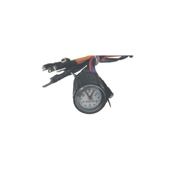
8.Simulation of Resistance Signal
This instrument equipped Precision Multi-turn pointer potentiometer (Fig.16) (ACCES.7), used for simulate the resistance signal. This potentiometer designed with variety of transfer connectors (Fig.22), convenience for diagnosis.
![]()
9, Signals Combinatorial Output
The 7 signals (sinusoidal, square-wave, X+Y signal, voltage signal, oxygen sensor signal, resistance signal and PWM signal) can be output simultaneously. If need this kind of application, please choose the eight-line components (ACCES.6) and potentiometer connectors (ACCES.7), access to Auto electronic control system as needed. Used for diagnosis difficult fault.
Recommended Products